PS-CAL Software Calculations Explained
Veröffentlicht Februar 23, 2023 von Advanced Energy Editor
Automated Calibration of RF Power Sensors: PS-Cal Calibration Factor, Mismatch, and Uncertainty Calculations Explained
The PS-CAL software solution automates calibration of RF Power Sensors to a high degree of accuracy. It executes the following three complex mathematical calculations: The Calibration Factor, The Mismatch Factor, and Uncertainty. This post discloses the calculations within the software so metrologists and engineers can validate the system, document the calibration process, and report results.
This solution is particularly useful for test engineers and/or metrologists with calibration responsibilities for sensitive equipment such as RF power sensors. In many cases, the equipment is utilized by third party calibration organizations where metrologists must often provide documentation for the calibration results they deliver. Likewise, metrologists at military facilities will be able to document and validate their calibration results.
PS-CAL delivers multiple advantages. It automates the calibration process with the capabilities to control the equipment during the calibration process, make the necessary measurements, and perform the complex calculations. It then generates a calibration report. A unique feature of PS-CAL is the flexibility to calibrate sensors from many manufacturers, reducing the need for dedicated proprietary calibration systems.
- The Calibration Formulas
- Calculating the Power Sensor Calibration Factor
- Determining the RF Power Level
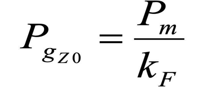
- Apply power from an RF power source/generator (Pgzo) into an RF power sensor.
- The power from the source is equal to the power measured by the power sensor (Pm) divided by the power sensor correction or calibration factor (kF). This assumes that the impedances between the two devices match, which results in no reflection (mismatch) factor.


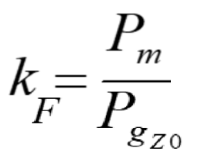
- Determining the Power Sensor Calibration Factor
- To calculate the formula above, one must first determine the calibration factor (kF) of the power sensor. To do so, divide the measured power reading from the power sensor (Pm) by the known accurate power from the power source (Pgzo), as follows. This calculation still assumes a perfect impedance match.

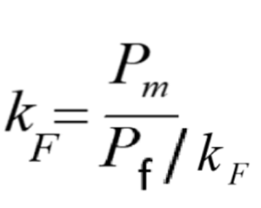
- In this power sensor calibration system, the RF source (generator) is monitored by an AE-TEGAM feedthrough power standard to provide an accurately known RF power level. This feedthrough standard will be considered as the RF power source (Pf) in the following calculations.
- The RF power source (Pf) requires a correction factor (kF). This must be applied to its reading to achieve an accurate power source value as follows.

- To calculate the formula above, one must first determine the calibration factor (kF) of the power sensor. To do so, divide the measured power reading from the power sensor (Pm) by the known accurate power from the power source (Pgzo), as follows. This calculation still assumes a perfect impedance match.
- Understanding the Reflection (Mismatch) Factor
- Up to this point, the calculations assume a nearly perfect impedance match between the two devices. However, during real world situations, some impedance variation (mismatch) will always exist between the RF power source (AE-TEGAM feed-through standard) and the RF power sensor (DUT)
- The resulting mismatch causes some of the power to reflect back to the RF power source and therefore not be applied to the RF power sensor.
- The reflection (mismatch) factor is derived from a complex set of values made up of both the amount (magnitude) and the direction (phase) of the reflection of both devices. The reflection values for each device are determined by measurements made with a vector network analyzer (VNA).
- PS-CAL uses the reflection factors for each device to calculate the reflection (mismatch) correction. The software then applies the correction to determine the calibration factor of the power sensor.
- The VNA, used as a 1-port device, measures and collects the reflection data directly from the power sensor. The collected reflection data, taken from VNA scattering parameters, is also referred to as the S11 Rho data. PS-CAL will utilize a VNA, when available and the appropriate procedure is selected, to collect the reflection data during the power sensor calibration process.
- Collecting the reflection data for the source monitor (AE-TEGAM feedthrough standard) requires greater complexity. The data is derived from a set of measurements taken on the feedthrough standard’s internal power splitter during the standard’s calibration process. This reflection data is part of the electronic calibration standards file utilized by PS-CAL when the AE-TEGAM feedthrough standard has been selected.
- Calculating the Mismatch Correction
- The Mismatch Correction combines the reflection data for the two devices as follows:
- Combine the linear rho magnitude (p) of the source (p1) and sensor (p2) by multiplying.
- Combine the phase in degrees (Ф) of the source (Ф1) and the sensor (Ф2) by adding.
- Convert the combined phase to radians.
- Convert the Polar data to rectangular (real/imaginary) values by taking the cosine of the combined phase in radians x the combined magnitude (real) and the sine of the combined phase in radians x the combined magnitude (imaginary).
- Convert the rectangular coordinates (1 – real) and (-1 x imaginary)
- Square the absolute value of the real and complex numbers (converted real^2) and (converted Imaginary^2).
- Combine the squared values of the complex numbers by adding the squared real and imaginary values together to determine the combined mismatch correction factor (r).

- The Mismatch Correction combines the reflection data for the two devices as follows:
- Apply the Reflection (Mismatch) Correction Factor
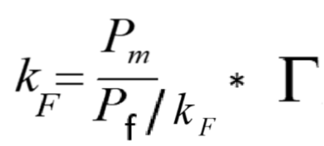
- Apply the calculated combined mismatch factor (r) above to the calculated sensor correction factor as shown in the formula below to determine the sensor’s corrected calibration factor (kF).

- Note that the combined mismatch and calibration factors need to be calculated for each frequency point required for the sensor calibration.
- Apply the calculated combined mismatch factor (r) above to the calculated sensor correction factor as shown in the formula below to determine the sensor’s corrected calibration factor (kF).
- Calculating Uncertainty
- PS-Cal calculates the “system” uncertainty by taking the “root-sum-square” of the following contributors:
- The uncertainty of the RF standard at the set frequency
- The uncertainty of the standard power meter
- The uncertainty of any attenuators/adaptors at the set frequency
- The uncertainty of the DUT power meter
- The standard deviation of the test runs (if more than one)
- The standard deviation of the measurement samples of the 1830A
- The calculated mismatch uncertainty from the S11 (rho) test
- PS-Cal calculates the “system” uncertainty by taking the “root-sum-square” of the following contributors:
- Summary: PS-Cal Calculations
- The Calibration Factor, Mismatch, and Uncertainty formulas performed automatically in the PS-Cal software:
- Sensor Calibration Factor:

- Mismatch Factor:

- Uncertainty: Root-Sum-Square of contributors
- Sensor Calibration Factor:
- The Calibration Factor, Mismatch, and Uncertainty formulas performed automatically in the PS-Cal software:
The PS-Cal software solution automates the power sensor calibration process and executes these complex mathematical calculations. Contact Advanced Energy to learn more about what PS-Cal can do for you.
