The cables that power production sites in automated welding processes must withstand the harsh conditions present in a welding environment. These include high temperatures, abrasion, and exposure to chemicals. Resistance testing provides welding quality technicians with the means to verify the reliability and durability of the welding cables. In turn, maintaining the integrity of the cables assures ongoing high quality production line welds.
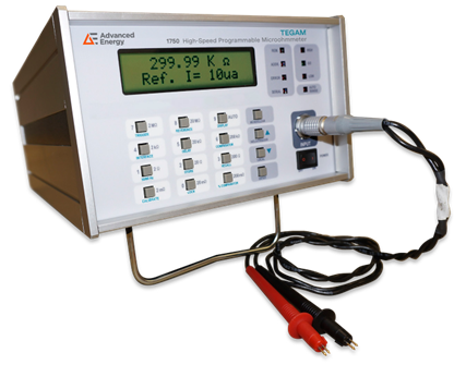
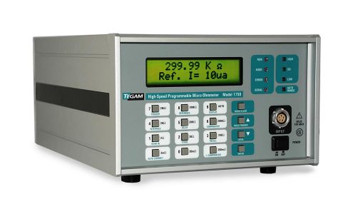
The basic test measures the electrical resistance of robotic welding cables to qualify that the cable under test falls within the manufacturer’s specified range. This test is critical because excessive resistance can cause a voltage drop, resulting in poor welding quality, out-of-spec parts production, and damage to the equipment. This paper discusses the process of resistance testing of robotic welding cables using the
Advanced Energy's TEGAM 1750 micro-ohmmeter. It will also identify the factors that can negatively impact the results.
When an accurate micro-ohmmeter records significantly higher resistance than the cable’s original or expected resistance, an out-of-specification reading indicates that the cable has likely developed a fault. Such a fault caused by a break in the cable or corrosion, if not already causing faulty welds, will likely soon compromise the weld process and result in product quality issues. In short, an out-of-spec resistance reading delivers the red flag to replace the welding cable as a necessity to maintain ongoing production quality.
Measurement Process
It’s important to take resistance measurements at room temperature when the cable is not in use. A high resistance measurement when the cable is in use could indicate a different issue, such as a poor connection or insufficient current capacity. If the resistance of the welding cable measures higher than the original specification, inspect the cable for signs of damage and determine if replacement is necessary.
Testing Procedure:
Accurate resistance testing of robotic welding cables requires a micro-ohmmeter. To conduct a resistance test, follow these steps:
- Disconnect the cable from both the welding power source and the welding torch.
- Be sure the cable is clean and free from any debris or contaminants that may impact test results.
- Connect the two micro-ohmmeter probes, one to each end of the cable.
- Activate the micro-ohmmeter and record the resistance reading.
- Verify whether the resistance reading just obtained meets the manufacturer’s specification. If not, replace the cable.
Factors That Can Impact Resistance Testing
Factors that can potentially skew the welding cable inspection results include:
- Temperature: The resistance of a cable increases as the temperature increases. Therefore, be sure to test the cable at the same temperature as used in the welding process. If the cable is tested at a different temperature, the resistance reading will not be accurate.
- Length of the cable: The longer the cable, the higher the resistance. Therefore, the resistance testing of a longer cable will produce a higher resistance reading than a shorter cable of the same type.
- Cross-sectional area of the cable: The cross-sectional area of the cable affects its resistance. A cable with a larger cross- area will have lower resistance than a cable with a smaller cross-sectional area.
- Type of cable: Different types of robotic welding cables have different resistance values. Therefore, check that the cable being tested is the correct type for the welding application.
- Wear and tear: The resistance of a cable increases over time due to wear and tear. If the resistance increases, it will likely result in weld failures due to insufficient power reaching the weld site. Therefore, be sure to inspect the cable for any signs of damage or wear before testing it. If an automated welding production station operates on a multi-shift schedule, it is important to conduct regularly scheduled resistance testing and cable inspections.
Conclusion: A Crucial Quality Process
Resistance testing of robotic welding cables is a crucial process that assures their reliability and durability. The
Advanced Energy's TEGAM 1750 micro-ohmmeter, recognized as the fastest precision micro-ohmmeter in the industry, now ranks as the number one choice in manufacturing environments. The instrument applies multiple techniques to achieve its impressive accuracy of up to 0.05%. The high-speed 1750 can set-up, zero-out thermal error, acquire data and make its first reading in less than 12 milliseconds. The instrument is the premier programmable micro ohmmeter. It operates using either the front panel or over the bus via multiple interfaces including IEEE-488, RS-232C, and RS-422 to maximize programming efficiency. The same programming command set is used for each interface. Front panel indicators provide continuous status of all monitored operations.
See
Advanced Energy's TEGAM 1750 micro-ohmmeter!

.png?resizemode=force&maxsidesize=408)


.png?resizemode=force&maxsidesize=128)


.png?resizemode=force&maxsidesize=128)


.jpg?resizemode=force&maxsidesize=884)