
EMI Management for Board-Mounted Power Modules
投稿 5月 08, 2026 によって Andy Brown
Blog Summary
- BMP modules are compact but generate EMI: Switched‑mode power conversion in board‑mounted power modules (BMPs) produces both radiated and conducted EMI due to switching activity, PCB traces, and unshielded magnetic components acting like antennas.
- EMI must be managed at the system level: Radiated noise (30 MHz–1 GHz) and conducted noise (150 kHz–30 MHz) can interfere with nearby circuitry and power lines, so designers rely on system‑level solutions like shielding, grounding, and enclosure design rather than fully enclosing the module itself.
- Mitigation combines layout and filtering techniques: Effective EMI reduction involves shielding, solid ground planes, careful PCB layout, and external input filters (with proper component selection and placement), ensuring compliance with standards such as EN 55022 Class B.
Board-mounted power modules offer a convenient and compact solution to system power-supply challenges. However, any switched-mode power converter can be a source of electromagnetic interference (EMI), which needs to be correctly managed.
This blog examines EMI noise in and around board-mounted power modules and outlines steps to mitigate any risks associated with both radiated and conducted EMI.
Switched-mode power conversion is essential for almost every electronic system. Board-mounted power (BMP) modules offer a proven and effective method to quickly and easily provide power-conversion in compact form factors to generate useful voltages. However, switched-mode power conversion is also a source of EMI in the form of radiated and conducted noise. While soft-switching techniques and optimized layouts reduce interference, additional steps must be taken to minimize EMI when deploying BMP modules.
Mitigating both radiated noise with shielding and conducted noise through the insertion of suitable filters in power lines and connections ensures that the final product functions correctly and meets stringent electromagnetic compatibility (EMC) regulations such as EN 55022 Class B.
How can BMP Modules be a Source of EMI?
To achieve a compact footprint and meet power density goals, DC-DC module designers often turn to planar transformers. The transformer windings are created as tracks in the BMP’s PCB and the core of the component is clipped around these traces to complete the magnetic circuit (see figure 1).
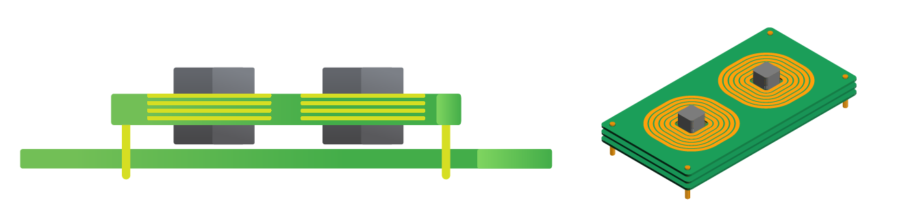 Figure 1. Transformer windings are a source of noise in BMP modules.
 The windings of the transformer and inductor, as the principal magnetic components, are un-shielded and so provide an effective antenna for transmitting radiated emissions at the switching frequency and the switching frequencies harmonic frequencies. The cores of the magnetics are also unscreened and will produce emissions at these frequencies. In addition, the PCB traces that carry the power and switching waveforms act as antennas that contribute to the emissions from the module.
While a six-sided metal casing could prevent EMI radiating from the module, these are seldom used. A full metal casing tends to drive up the module’s cost, is not beneficial in increasing power-conversion density (Watt/cu-in) and is largely not necessary as EMC regulations apply only at the system level, not at module-level. From this standpoint, an open power module is usually satisfactory if the complete system is housed in a metal enclosure (figure 2).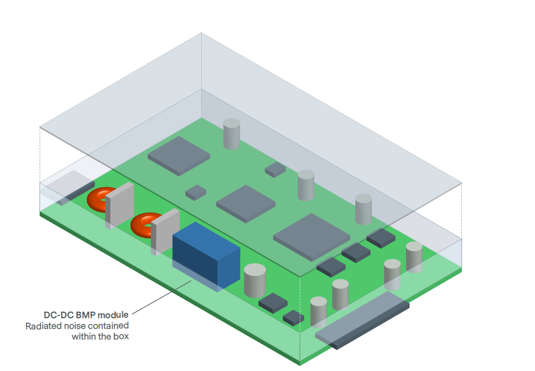 Figure 2. The casing of the final product provides the screening and contains any radiated EMI generated by the module.
While a six-sided metal casing could prevent EMI radiating from the module, these are seldom used. A full metal casing tends to drive up the module’s cost, is not beneficial in increasing power-conversion density (Watt/cu-in) and is largely not necessary as EMC regulations apply only at the system level, not at module-level. From this standpoint, an open power module is usually satisfactory if the complete system is housed in a metal enclosure (figure 2).
Figure 2. The casing of the final product provides the screening and contains any radiated EMI generated by the module.Radiated and Conducted EMI
Let’s delve deeper into the radiated and conducted EMI associated with BMP modules.
Radiated emissions occur at the fundamental frequency (converter switching frequency) and their associated harmonics. Specifications, such as the CISPR series, that apply to all electronic equipment including domestic appliances, power tools, computers, and televisions reference the norms stated in EN 55022 class B. For radiated emissions, EN 55022 class B considers noise in the frequency range from 30 MHz to 1 GHz.
The radiated EMI field from the module is emitted in all directions, although the predominant effect to the application is usually vertically above and below. Naturally, the field intensity is highest near the module and decreases when moving further away, although the distances involved can be many times the dimensions of the DC-DC converter itself.
Any tracks or wires close to the input side of the module will pick up the noise and this will manifest itself as conducted emissions on the input to the application. If tracks or components are placed under the BMP module, these can be particularly affected (figure 3). 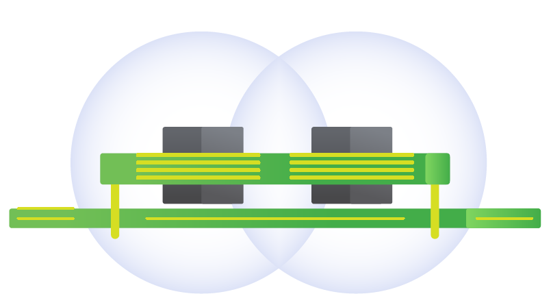 Figure 3. Radiated emissions from an unshielded BMP can affect circuit elements.
Figure 3. Radiated emissions from an unshielded BMP can affect circuit elements.
has the effect of inhibiting much of the spectrum in the vertical direction. In conjunction with this shield, as per figure 4, designing the upper layer of the PCB with a large copper area directly beneath the BMP module and connecting to ground prevents emitted radiation from entering the PCB to interfere with the circuit tracks and components.
Figure 4. Grounded module top plate and PCB-plane block radiated EMI.
Figure 4. Grounded module top plate and PCB-plane block radiated EMI.
AC-DC BMPs deserve special consideration, as the module is likely to be located close to the input connections for an application. A lack of shielding and consideration of EMI radiation from the module can allow radiated interference to induce conducted noise in these connections. Typically, plastic module enclosures fail to address or affect any screening of those emissions, but the use of case kits may be an option. Advanced Energy’s AC-DC BMPs (for example the AIF-500) are available with case kits that can be easily and quickly applied to prevent emissions of AC-DC modules that are coupled into the power supply conductors (figure 5).
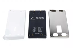
Figure 5. Advanced Energy case kit for AIF AC-DC modules.
Figure 5. Advanced Energy case kit for AIF AC-DC modules.
When it comes to conducted emissions, the input-pins of the module are considered to be the noise-generator. EN 55022 class B considers conducted emissions in the frequency range of 150 kHz to 30 MHz. It also specifies that no items of equipment are allowed to affect other equipment connected to the same power supply. So, any noise generated by the BMP module must be prevented from feeding back into the application power source. This necessitates an input EMI filter, which is implemented in the application as there is usually no room to accommodate the components inside the BMP module. The filter must be placed externally to the module on the host PCB.
The design of the filter, including component types and values, is driven by factors including the module’s switching frequency and power rating. Designers may elect to build their own filters from discrete components or source a standard or custom filter from third parties. Figure 6 shows a typical input filter schematic and bill of materials.
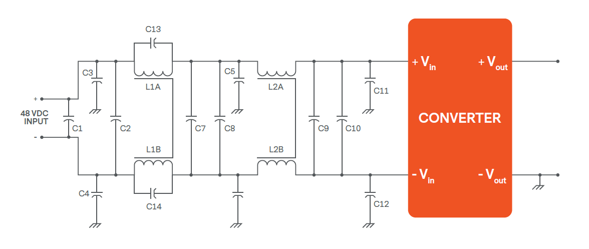 Figure 6. Generic EMI filter design.
The design of the filter, including component types and values, is driven by factors including the module’s switching frequency and power rating. Designers may elect to build their own filters from discrete components or source a standard or custom filter from third parties. Figure 6 shows a typical input filter schematic and bill of materials.
Figure 6. Generic EMI filter design.
Proper filter design should consider more issues than schematic and component values. Selection of component types and the layout and realization of the filter are critically important to the successful operation and effectiveness of the filter. Some guidelines include placing capacitors for high-frequency decoupling near to the module, the use of surface-mount components to minimize aerial effects and deploying toroidal inductors to keep the field within core.
Common-mode chokes should also be placed between current carrying and signal lines. Using RC snubbers is also an effective technique to dampen ringing.
Track shapes need to have curved corners to prevent unnecessary and easily avoidable emissions. Careful layout to force noise-carrying conduction paths past de-coupling capacitors is critical to performance.
To reduce cost, it may be possible to use one filter with two BMP modules. This is particularly easy to accommodate if multiple instances of the same module are used in a current sharing or redundant arrangement. Figure 7, for example, shows a reference design developed by Advanced Energy’s engineering team to combine a single surge suppressor and EMI filter with two AIF-500 AC-DC BMP modules.
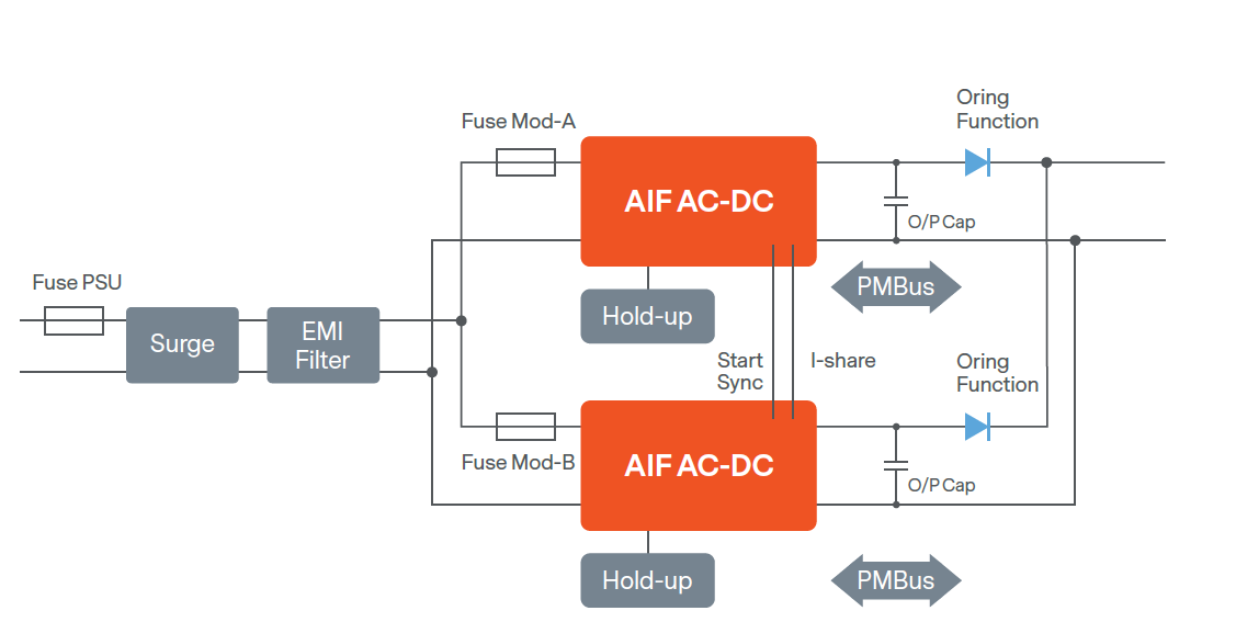 Figure 7. Sharing an EMI filter with two or more BMP modules.
Common-mode chokes should also be placed between current carrying and signal lines. Using RC snubbers is also an effective technique to dampen ringing.
Track shapes need to have curved corners to prevent unnecessary and easily avoidable emissions. Careful layout to force noise-carrying conduction paths past de-coupling capacitors is critical to performance.
To reduce cost, it may be possible to use one filter with two BMP modules. This is particularly easy to accommodate if multiple instances of the same module are used in a current sharing or redundant arrangement. Figure 7, for example, shows a reference design developed by Advanced Energy’s engineering team to combine a single surge suppressor and EMI filter with two AIF-500 AC-DC BMP modules.
Figure 7. Sharing an EMI filter with two or more BMP modules.
Conclusion: Design EMI Compliant Power Systems with Confidence
Integrating switched mode power converters into any system requires effective EMI management to control noise generated at the converter switching frequency and its harmonics. By identifying interference sources early and applying a combination of mechanical techniques (such as shielding, careful layout, minimized loop areas, solid ground planes) and electrical techniques including filtering, decoupling, damping, and bypassing, designers can achieve reliable system performance while meeting EMC requirements such as EN 55022 Class B.
As a leading supplier of DC DC and AC DC board mounted power modules, Advanced Energy supports OEMs beyond the converter itself. This support includes EMI reduction case kits, reference designs and filter calculation tools, and hands on engineering assistance throughout design, testing, and certification, helping teams reduce risk, minimize test iterations, and accelerate time to approval.
To explore Advanced Energy’s EMI mitigation resources, tools, and expert support to accelerate design to certification, and learn more about Advanced Energy AC-DC BMP module offerings, visit: AC-DC BMP | Advanced Energy.
You may also find these resources useful:
• Why EMI Matters in BMP Modules
• EMI Management in DC-DC BMP Modules

Andy Brown
Advanced Energy
Andy Brown currently serves as the Director, Technical Marketing for DC-DC products, a position he has held for the past 11 years. Prior to this position, Andy served as a Senior Field Applications Engineer at Astec Power for 13 years, focusing on Telecom. He has more than six years’ experience in design engineering. Andy also holds a BEng Honors degree in Electrical and Electronic Engineering from the University of Hertfordshire.
その他の投稿 Andy Brown